

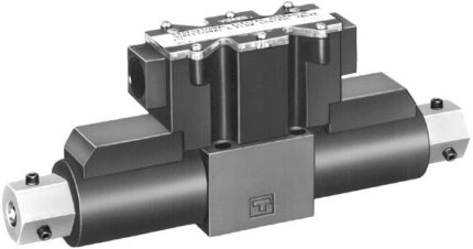
EHDFG 01/03 Proportional Directional and Flow Control Valves
These valves incorporate two control functions – flow and direction – which simplify the hydraulic circuit composition and therefore the cost of the system is reduced.

ELDFG High Speed Proportional Directional & Flow Control with On Board Electronics
Closed loop, high response type proportional electro-hydraulic directional and flow control valves with on board electronics. Two direct type models with a maximum rated flow rate up to 80 l/min (@.ΔP=1MPa) are available. Two different available models of two stage OBE valves have a maximum rated flow rate up to 500 L/min (ΔP=0.5MPa (72 psi) at each port).
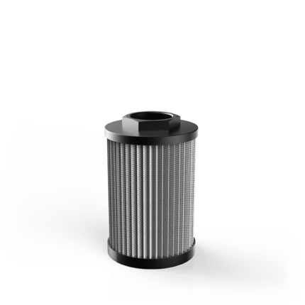
ESA – ESB
Qmax 600 l/min
MATERIALS
Connector: Polyammide
(Aluminium for ESA & ESB 51 – 52)
End cap: Polyammide
(Zinc plated steel for ESA & ESB 51 – 52)
Bypass valve: (ESA) Polyammide
Magnetic core: (ESB) Syntherized magnetic material
PRESSURE
Collapse, differential: 100 kPa (1 bar)
BYPASS VALVE
Setting: 30 kPa (0,3 bar) ± 10%
WORKING TEMPERATURE
From -25° to +110° C
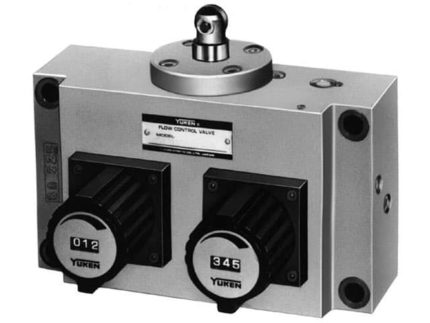
Feed Control Valves (UCF1(2)G-01(03)(04))
These valves are the combination of flow control valve, a deceleration valve and a check valve and used mainly for controlling rapid traverse and feed cycles machine tools. Switching from rapid traverse to feed is made by a cam operation, and fine feed control is accomplished by dial rotation regardless of pressure and oil temperature variation. Rapid return is free of cam actuation.
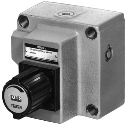
Flow Control & Check (F(C)G)
These valves are pressure and temperature compensating type valves and maintain a constant flow rate independent of change in system pressure (load) and temperature (viscosity of the fluid). They control flow rate of the hydraulic circuit and eventually control speed of the actuator precisely. Valves with an integral check valve allow a controlled flow and reverse free flow. Repeated resetting can be made easily with a digital readout.
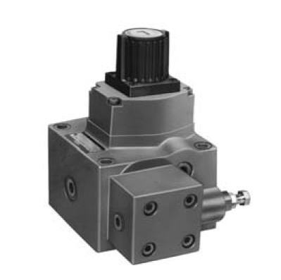
Flow Control and Relief Valves (FBG-03/06/10)
These valves are flow control valves having the functions of metre-in type flow control and pressure control. Inlet pressure is always maintained 0.6 MPa (87 PSI) higher than the load pressure.
In a conventional flow control method, power consumption is wasteful since the pump pressure goes up to the preset system pressure regardless of the load pressure. While, the power saving valves control the pump pressure by maintaining a differential pressure as little as 0.6 MPa (87 PSI) against the load pressure, thereby, the power can be remarkably saved.
Moreover, with the temperature compensator, a stable flow control can be made regardless of oil temperature. Setting and repeat setting of flow can be made easily with an adjustment knob having digital scales.
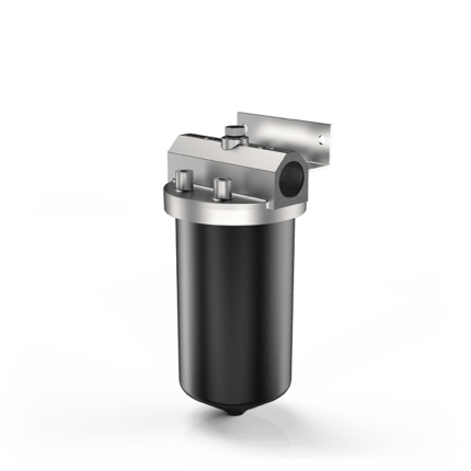
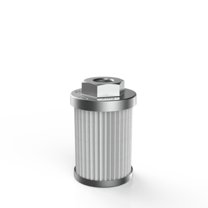
FMA – LFM
Pmax 7 MPa
Qmax 600 l/min
MATERIALS
Head: Aluminium alloy
Bowl: Cold formed steel
Seals: NBR Nitrile (FKM Fluoroelastomer – on request)
Indicator housing: Brass
PRESSURE
Max working: 0,7 MPa (7 bar)
Collapse, differential for the filter element (ISO 2941): 300 kPa (3 bar)
WORKING TEMPERATURE
From -25° to +110° C
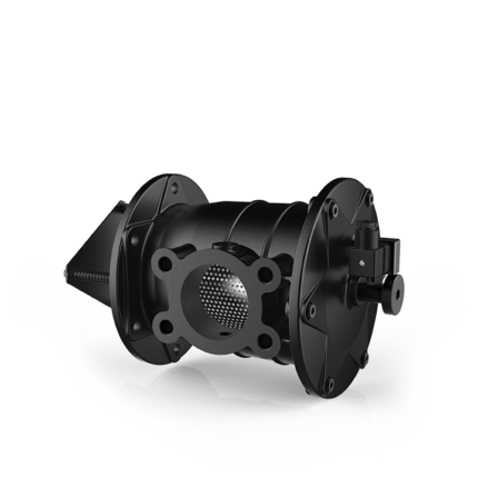
FSC – FSB
Qmax 500 l/min
MATERIALS
Housing: Aluminium alloy
FSC31 & FSC41
Cover & head: Aluminium alloy
Bowl: Polyammide
FSC71 & FSC81
Cover & housing: Aluminium
FSC51 & FSC61
Housing: Steel | Cover: Aluminium
Shut-off valve: Polyammide
Seals: NBR Nitrile
(FKM – on request fluoroelastomer)
Indicator housing: Brass
PRESSURE
Collapse, differential for the filter element (ISO 2941): 100 kPa (1 bar)
WORKING TEMPERATURE
From -25° to +110° C